Nos Services
Dépannage informatique sur site ou à domicile pour particuliers et professionnels - Maintenance de votre parc informatique - Sauvegarde - Récupération de données - Installation de réseaux - Assistance à distance
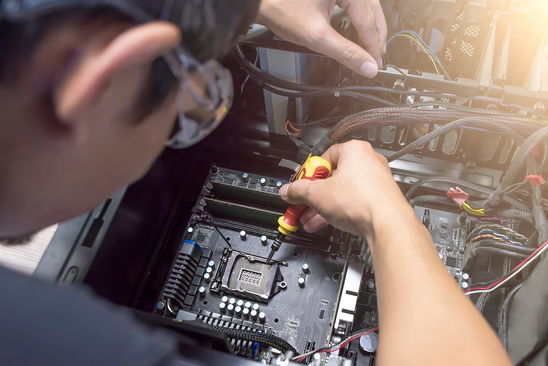
Dépannage Informatique
Dépannage sur site ou à domicile - Pour particuliers et professionnels - Mac & PC.
- PC en panne, plantage, virus, problème de connexion Internet.
- Réparation de votre ordinateur fixe ou PC portable.
- Plus besoin de transporter son matériel ni de se déplacer.
- Intervention sur site rapidement et sur simple appel.
Maintenance de votre parc informatique
- Installation et mise à jour de logiciels
- Nettoyage de Windows (fichiers temporaires, malwares, registre)
- Installation de matériel (imprimante, mémoire etc.)
Assistance à distance
Vous avez un problème avec votre ordinateur mais votre connexion internet fonctionne encore, nous pouvons faire un dépannage informatique en ligne grâce à un logiciel de prise en main à distance. Vous pouvez ainsi profiter de nos services même si vous êtes en dehors de la zone d'intervention.
En savoir Plus
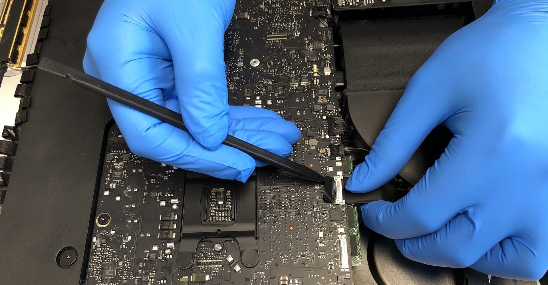
Matériels & périphériques
Nous fournissons dans la limite du possible,
toutes les pièces pour réparer votre ordinateur,
nous préferons changer une pièce que de tout
changer.
Nous réparons :
- Les PC de bureau, les Serveurs, les imprimantes, les scanners.
- Les disques dur sont changés par des disques dur SSD, qui sont beaucoup plus fiable et rapide.
- les alimentations et prises des ordinateurs portable.
- Les écrans, les claviers, les charnières ...
- et bien plus encore...
Matériel Neuf
Nous fournissons et installons tout type de matériel informatique neuf : PC, Mac, Serveur, Imprimante... et nous vous le garantissons 5 ans.
Recyclage du matériel informatique
Le Centre de Service se charge de la récupération et du recyclage du matériel que vous n’utilisez plus. Tout ordinateur, imprimante, périphérique, écran, clavier, câble, etc... Nous nous chargerons de le recycler ou le donner à des institutions.

Sauvegarde
- Mise en place d'une sauvegarde locale ou externalisée
- Configuration de votre NAS
- Onduleur
Récupération de données
- Votre disque dur ne fonctionne plus ?
- Vous avez effacé un fichier important par mégarde et vous avez vidé la corbeille ?
- Confiez-nous votre disque pour tenter de récupérer vos données.